| Previous | Main | Up | Next |
The board has two LEDs. Sample code to alternately blink the red (LED1) and the green (LED2) is shown. There are many different ways to program the P1OUT pins, several are shown in this code (all but one commented out). Instead of using the simple delay loop from before we are using a more precise intrinsic function. It sets how many clock cycles to delay and won't be optimized out by a compiler. This still varies the blink rate depending on input voltage, which determines clock frequency.
#include "io430.h"
#include "intrinsics.h"

int main( void )
{
   // Stop watchdog timer to prevent time out reset
   WDTCTL = WDTPW + WDTHOLD;

   P1DIR |= 0x01; // set p1.0 to output
   P1DIR |= 0x40; // set p1.6 to output

   // Turn on the first LED, the other stays off
   P1OUT = 0x01; // set p1.0 on (red led)

   // Main Loop - run forever
   for (;;)
   {
      // Toggle P1.0 and P1.6 using exclusive-OR

      // The first option uses a single hexadecimal value
      // P1OUT ^= 0x41; // Used in most TI provided examples

      // This option uses bit shifts. It looks a little more
      // complicated but is optimized by the compiler so it's
      // just as efficient.
      // P1OUT ^= ( 1 | (1 << 6)); // Common approach

      // This one is a little more understandable
      // P1OUT ^= (BIT0 | BIT6); // Depends on compiler defines

      // A minor variation of the above
      // P1OUT ^= (BIT0 + BIT6); // More novice friendly

      // This one is very explicit and easy to follow.
      // However the two lines are not likely to be optimized
      // into one, so it is a little less efficient.
      // P1OUT_bit.P0 ^= 1; // Specific to IAR defines
      // P1OUT_bit.P6 ^= 1;

      // This one is understandable and easily optimized
      P1OUT ^= (P0 + P6); // Depends on compiler but typical

      // Explicit delay
      __delay_cycles(500000);
   }
}
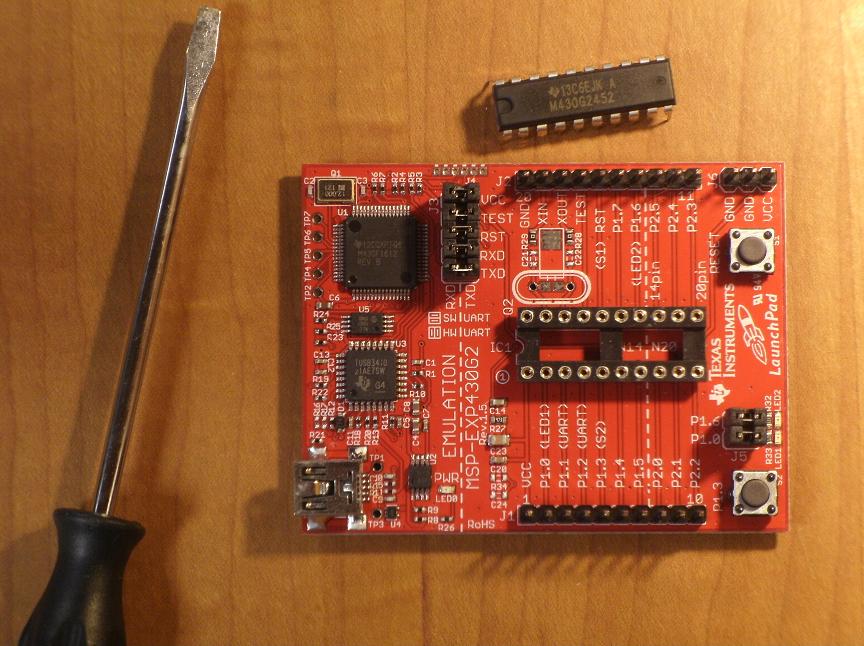
To remove the 2553 and insert 2452, gently lift the 2553 from the socket and keep parallel with the board to avoid bending pins. Use a small flat screwdriver or IC remover to lift from both ends at the same time - don't pry up one end. Use the indent on the chip to insert it correctly.
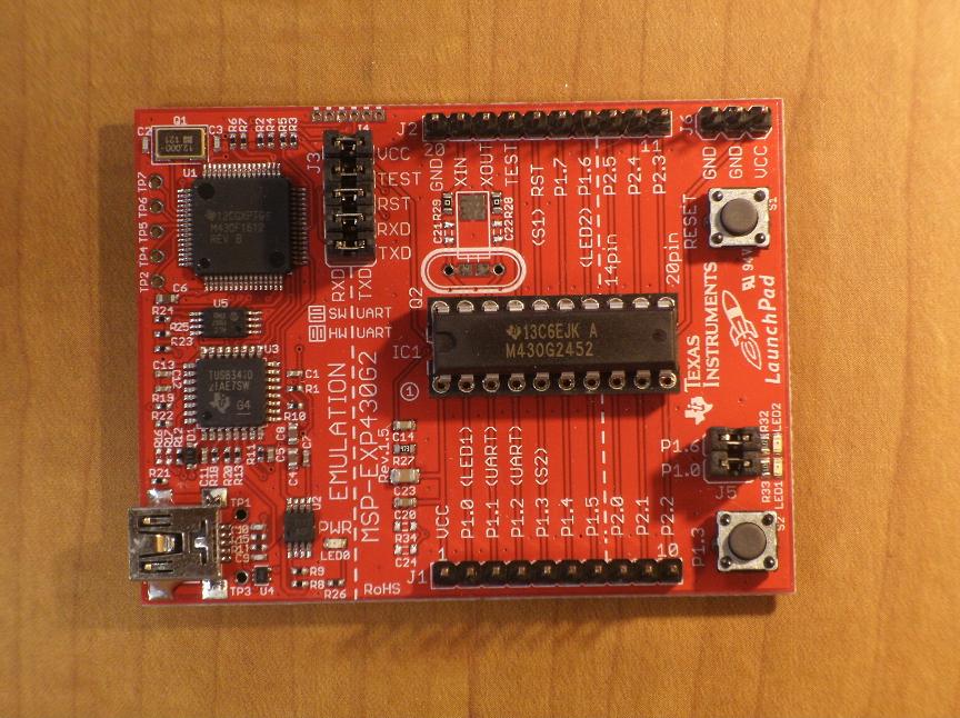
Swapping out your 2553 with the 2452 or a chip you buy is easy. Don't panic if the pins are a little bent. Gently straighten the pins and they should be fine. Notice that the processor socket on the board has a small indent on one end. The chip also has a small "U" indent. This is how you know which way to insert the chip. Insert it backwards and it won't work.
The G2553 includes 16kb of flash, 512b of RAM, and two Timer_A3 modules, and the USCI module. The G2452 has 8kb of flash, 256b of RAM, one Timer_A3 and the USI module. There is also a cost difference - $2.30 for a G2553 and $1.60 for a G2452, or $0.70 less (30% less).
|
|
|
|
Before connecting the board you need to install either IAR Workbench or Code Composer Studio. IAR Workbench includes the drivers for the LaunchPad. IAR Workbench is available from:
I recommend use of the first link (usually). Using iar.com will require registration for a license. With TI installer no license is needed.
These will install the drivers for the board. You could also install the drivers from slac435, which has the LaunchPad User Experience.
Following the links off ti.com/launchpad will lead you to both the TI installer (slac050) or to the IAR site. If you download the installer from the IAR site you'll need to register and request a license. The TI installer doesn't require this and is what we'll use.
Execute the installer from the slac050 zip file. Each version is indicated by two letters, the latest one as of today is slac050aj.zip - use the most recent one.
After running the installer and accepting all defaults, let the installer launch IAR Workbench. This is necessary to create the filetype associations so that double-clicking on an .eww file will launch the workspace in IAR Workbench.
This free version is the kickstart version. It is limited to 4k of code and does not include MISRA (Motor Industry Software Reliability Association) support. "Guidelines for the use of the C language in critical systems", or MISRA-C:2004 and the original MISRA-C:1998 are supported in the commercial version of IAR Workbench. This version is not time limited and with the exception of support for MISRA is the same as the full commercial version.
When you connect the LaunchPad board you should see four new devices on your computer. To confirm these are present you can use "Start", "Run", "devmgmt.msc" and look through the hardware list. All of the devices will have the indicated VID and PID.
The development environment should install the drivers automatically. Use slac435 drivers if they are missing or to use LaunchPads on a computer without installing IAR Workbench. You should see the following VID: 0451 and PID: F432 devices:
If instead you see prompts for finding the drivers then use slac435.
CCS (Code Composer Studio) includes MSP430Ware but IAR Workbench does not. Install MSP430Ware for easy access to a lot of TI documentation and examples.
The installer for MSP430Ware can be found here: http://www.ti.com/tool/msp430ware
The default install is to c:\ti. Once installed, the LaunchPad board details can be found at: C:\ti\msp430\MSP430ware_1_10_02_21\doc\boards\MSP-EXP430G2. Example code for the MSP430 LaunchPad can be found at C:\ti\msp430\MSP430ware_1_10_02_21\examples\devices\2xx.
| Previous | Main | Up | Next |