| Previous | Main | Up | Next |

|
For Exercise Three we write our own application and program the MSP430. Our initial application will blink one of the LEDs on the LaunchPad board.
A common initial embedded project is to blink a light. This is the "hello world" test for embedded developers. This project will blink LED1, the red light on your board next to the user button.
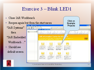
To get started, close IAR Workbench and any open windows. Now open IAR Workbench from the Windows "Start" button. This should open IAR Workbench with the "IAR Information Center for MSP430" displayed. You should see the initial screen displayed in the picture above. You could also open the information center from the "Help" menu but we need to start with a clean workspace.
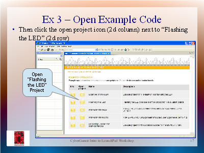
The information center has a lot of great material to look through. We're going to look at one of the example projects. Click on the "Example Projects" icon in the top row. You should see the following screen which lists several examples.

|
There are two columns on the left. The far left only opens an informational page about the project, the second actually opens the project for use. Open the "Flashing the LED" project.

|
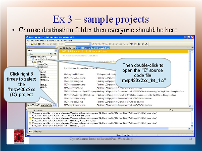
You should get a dialog asking for a destination folder. Accept the default. This workspace has many versions of this demo. We're looking for the simple version in "C" for our chip.
Click through the project tabs in the "Workspace" pane (tall one on the left) to find the x2xx sample in C. The tabs are at the bottom of the "Workspace" pane. The project we need is labeled "msp430x2xx (C)".
Once you've selected the project you will see the file list for this project in the "Workspace" pane. Double-clicking on the C file will open this so you can review the source code.
Your application window should look like the following:
|
|
Walk through the source code. Discuss why embedded systems have watchdog timers. It's a safety feature. There is an independent timer which counts down and resets the whole board if it reaches zero. Software must periodically reset the counter to avoid this. The timer is a way to restart an embedded system if something goes wrong, such as your code getting stuck or the processor halting.
Discuss the MSP430 ports, how they are multiplexed into pins. The chip only has 20 pins or 14 for some of the chips that can be used with this board. But the chip has a lot of features. So many of the pins have multiple uses. Your code must tell the chip what to use the pin for. In this code the port "P1.0" is being used as an output on pin 2.
| Source Code File | Web page view for printing |
This source code is really simple. There are lots of other examples with more complexity to help you learn. You should also try the tutorials in the Information Center as well.
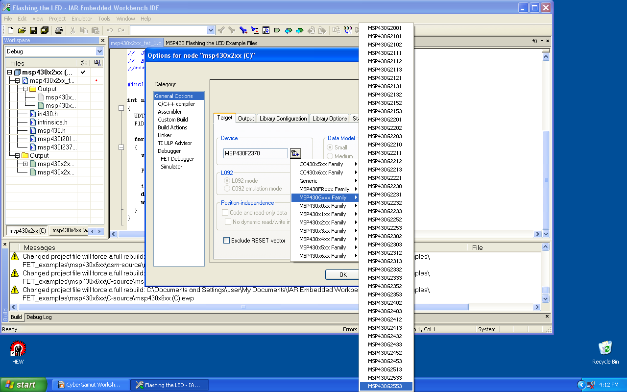
When you open any of the samples or code someone else provides you must confirm the proper device is selected. This is a project level setting, so select the top line in the workspace pane then open the project options. This is under the "Project" menu. You should see a window pop up labeled "Options for node msp430x2xx (C)" and the "General Options" category. If you don't see the general options where you can select the device then you didn't have the focus on the project in the workspace pane. These options are only available at the project level. If this is the case close the options window, select the top line (the one above the "C" file) and open project options again.

|
In the "Target" tab of "General Options" the top area is "Device". Clicking on the drop down icon to the right of the option box opens a list of device families. Select the "MSP430Gxxx Family" then slide you mouse to the right and go all the way to the bottom to select the last one, labeled "MSP430G2553".
Each chip (2553, 2452, etc) has different hardware and features. The compiler needs to know what chip you have so it can generate warnings and so it can use the right instructions and memory layout. This compiler supports all of the chips in the MSP430 family - about 500 of them. Look for the device number on top of the chip.
As we pointed out in Exercise Two, any file changes require rebuilding the project. Any time you change the device type you also need to rebuild the project. Use the same steps used in Exercise Two - select "Project" and then "Rebuild All".
You should see some messages in the bottom pane. Some of the errors and warnings you could see are using features the chip you selected doesn't support, or syntax errors in your code. In our case there should be no warnings and no errors.
Continuing the process we used in Exercise Two, the next step is to download our code onto the chip. Connect your LaunchPad to your computer. Select "Project", "Download", then "Download Active Application". You should see debug log messages, then "Download Complete", "Target reset", and no errors.
If you receive an error that the device does not match then you will need to change the device, rebuild, and download again. The error will cause a pop up window which states "Chosen derivative (MSP430....) and actual hardware (MSP430G2xx3) do not match. Continue to download?". To correct this error you will need to change the target device in the project options as we discussed above.
Reset your chip by pressng the "RESET" button (right button) on your LaunchPad and you should see a blinking LED. Success!!
|
|
The frequency of the blinking is controlled by the code and by the speed of the chip. These devices will run from 1.8V to 3.6V - but they run at different speeds unless you use the clock oscillator. In slas722 , the msp430g2x12 2x52 device manual, on page 20 the output voltage on ports is VCC minus 0.3V. Since VCC is at 3.547V when powered by USB the output on the pin is 3.247V. The schematics for the LaunchPad board show there is a resistor in the loop. So there is less voltage at the LED than this.
On to the fourth exercise - connecting the LaunchPad to a breadboard.
| Previous | Main | Up | Next |